Residential Site Plans That Show the City Exactly What You Are Building.
Get a clear, scaled property plan for a home addition, garage, deck, shed, fence, driveway, patio, pool, ADU, or other residential permit project. We research the parcel, map existing conditions, place the proposed work, document setbacks and site constraints, and prepare a drawing organized around your local permit requirements.
12–24 hoursTypical turnaround after complete intake
All 50 statesRemote property research and drafting
Get a Free Quote
Residential site plans from $129 · response within 4 business hours
Please complete all required fields.
Quote Request Received
We will review the property and respond within 4 business hours.
Official parcel researchProperty records and available mapping reviewed
Scaled permit drawingExisting and proposed improvements clearly shown
Local checklist reviewDrawing organized around the jurisdiction
Free correctionsReviewer-requested revisions within scope
Nationwide deliveryRemote drafting for US residential properties
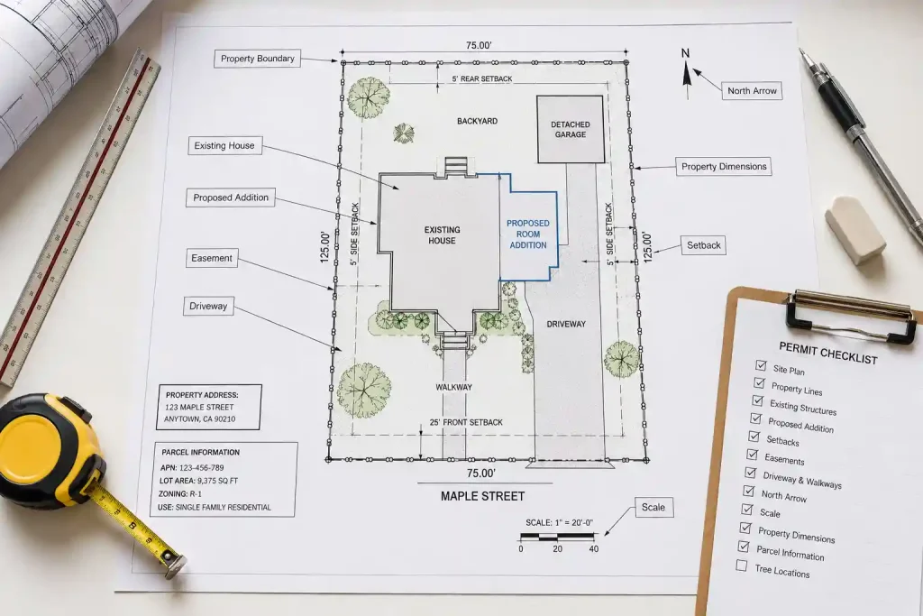
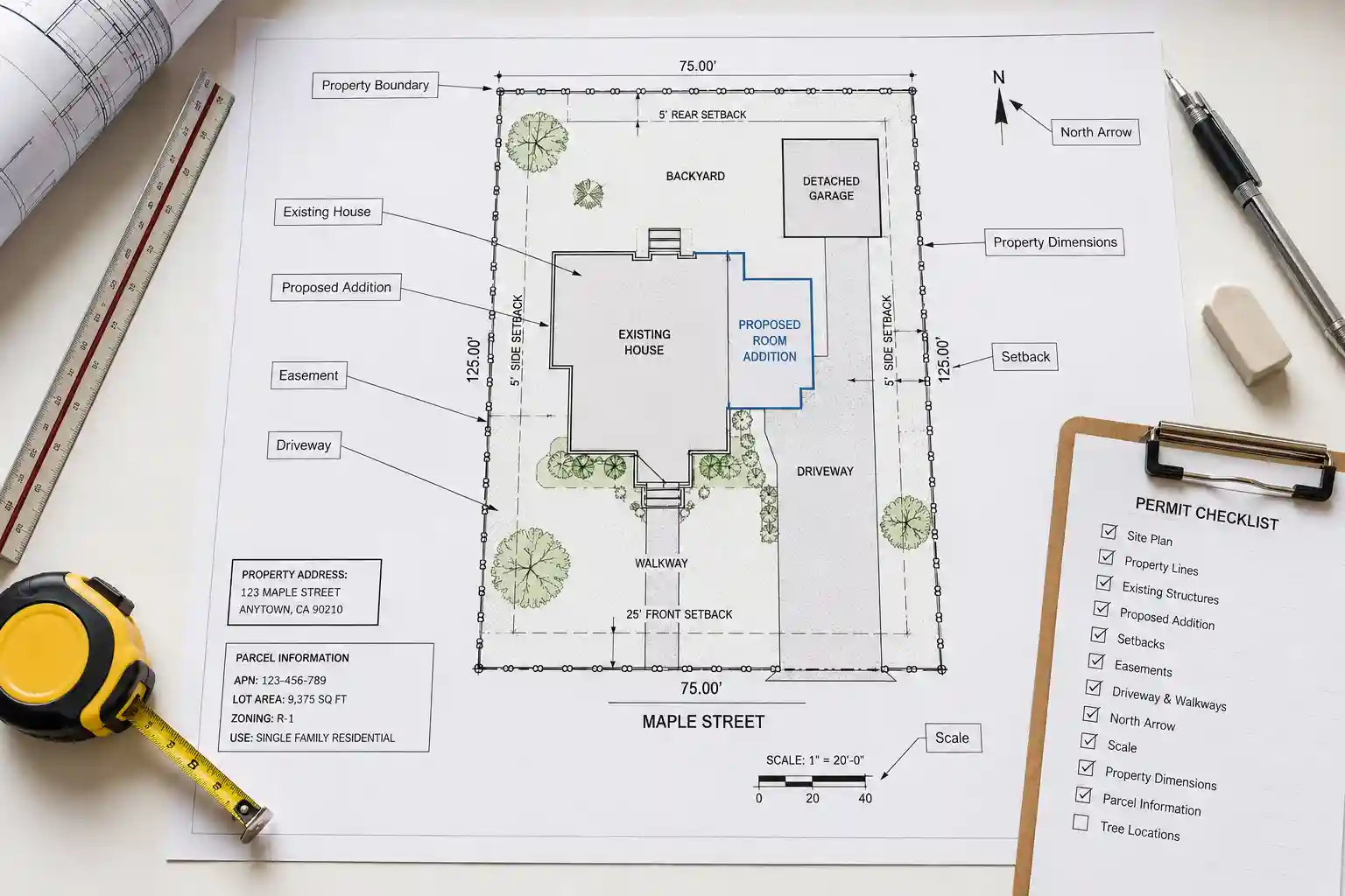
A top-down map of the complete residential propertyThe site plan connects the home, lot, proposed project, setbacks, access, easements, and utilities.
What Is a Residential Site Plan?
A Property-Level Drawing That Connects Your Project to the Land.
A residential site plan is a scaled overhead drawing of a home property. It shows the legal or mapped parcel boundary, the existing house and accessory structures, driveways, walkways, patios, decks, pools, fences, utilities, easements, and the proposed improvement that requires review. The plan allows a city, county, homeowners association, contractor, or design professional to understand where the project is located and how it relates to the rest of the property.
The site plan is often the first drawing a permit reviewer checks because it answers the basic zoning and placement questions. Is the addition far enough from the rear property line? Does the new garage fit outside an easement? Will the deck increase lot coverage beyond the allowed limit? Does a shed block a drainage path? Is a driveway wide enough and located correctly? Can a fence be installed without entering the public right-of-way? These questions cannot be answered by a floor plan alone.
A residential building site plan is different from an architectural floor plan. The floor plan shows rooms, walls, doors, and interior use. The site plan shows the entire lot from above. It places the building design into the property context and documents the dimensions the reviewer needs to evaluate setbacks, coverage, access, drainage, utilities, and surrounding conditions.
Site plans are used for new homes, home additions, detached garages, carports, decks, porches, patios, sheds, fences, retaining walls, driveways, pools, spas, solar equipment, ADUs, demolition, and many other residential construction projects. The level of detail depends on the local checklist and the complexity of the site.
City Permit Plans prepares the residential site plan component from available property information, project dimensions, photographs, existing plans, and surveys when provided. We also identify when the project requires a licensed survey, grading or drainage engineering, structural design, architectural drawings, or another document outside a standard drafting scope.
Property lines, dimensions, existing structures, and proposed work
Setbacks, access, easements, utilities, and site constraints
Scale, north arrow, notes, title information, and permit labels
Permit-office revisions included when they remain within scope
A Clean Property Diagram With Dimensions, Labels, and Permit Information.
Residential site plan examples can look simple or highly technical. The best drawing is not the one with the most lines; it is the one that communicates the correct property and project information clearly.
01 / PROPERTY OUTLINE
Parcel Boundary and Dimensions
The lot is shown as a scaled outline with available side lengths, frontage, street names, alleys, rights-of-way, and relevant easements. The parcel boundary provides the reference for every project setback and coverage calculation.
02 / EXISTING CONDITIONS
House and Site Improvements
The main residence, garage, sheds, pools, decks, patios, walks, fences, driveways, retaining walls, and other relevant features are shown so reviewers can compare existing and proposed conditions.
03 / PROPOSED PROJECT
New Work Clearly Distinguished
The addition, garage, deck, shed, fence, driveway, pool, ADU, or other improvement is labeled and dimensioned. Line weights, hatching, notes, or legends distinguish proposed work from the existing property.
04 / PERMIT DATA
Scale, North Arrow, Notes, and Title Block
A complete drawing includes the property address, drawing title, north arrow, stated scale, legend, sheet information, project notes, revision dates, and jurisdiction-specific checklist items.
Residential Projects We Support
One Property Plan Adapted to Many Home Improvement Projects.
Every project changes a different part of the property. The residential construction site plan is organized around the proposed work and the specific questions the permit office is likely to review.
Home Addition
Room Additions, Porches, and Building Expansion
A home addition site plan shows the existing house, proposed footprint, exterior dimensions, setbacks, lot coverage, access, patios, utilities, drainage considerations, and relationship to surrounding structures. It provides the property base for separate architectural and structural plans.
Garage & Accessory Structure
Detached Garages, Carports, Workshops, and Sheds
Accessory structures may have different setback, height, coverage, separation, driveway, fire, and utility rules than the main house. The plan shows the structure in relation to the residence, property lines, alleys, easements, parking areas, and other site improvements.
Deck, Porch & Patio
Outdoor Living Areas and Attached Improvements
Deck and porch plans often need the overall footprint, distance to lot lines, house connection, stairs, landings, setbacks, coverage, and relationship to utilities or septic systems. Raised structures and attached roofs normally require separate construction details and structural information.
Fence, Driveway & Site Improvement
Property-Line Work, Access, Walls, and Paving
Fences, gates, retaining walls, driveway extensions, new curb cuts, parking pads, walkways, and exterior improvements may affect sight distance, drainage, public right-of-way, utilities, easements, lot coverage, and neighborhood requirements. A scaled plan makes the proposed limits clear.
Residential Site Plan Checklist
What Reviewers Commonly Expect to See on the Drawing.
Local checklists differ, but these components form the core of a permit-ready residential site plan. We include the items that apply to the project and flag information that requires another professional.
01
Property Identification
Street address, parcel or lot information when available, owner or project name, drawing title, and jurisdiction references identify the property and the permit application.
02
Boundary and Lot Dimensions
Property lines, frontage, side and rear lot dimensions, rights-of-way, alleys, subdivision information, and easements establish the site limits. A survey is used when legal or field accuracy is required.
03
Scale and North Arrow
The plan uses a stated architectural or engineering scale appropriate for the parcel and sheet size. A north arrow and readable orientation help reviewers understand the property quickly.
04
Existing Structures
The house, garage, accessory buildings, pools, decks, patios, stairs, walkways, driveways, fences, walls, and other relevant improvements are located and labeled.
05
Proposed Work
The new project footprint is shown with dimensions, labels, and a clear graphic distinction from existing conditions. Demolition or relocation can be identified when part of the scope.
06
Setback Dimensions
Distances from the proposed work to front, side, rear, street-side, building, pool, septic, or other applicable reference points are shown according to the permit checklist.
07
Access and Circulation
Driveways, parking, gates, paths, steps, alleys, curb cuts, emergency access, and construction access may be shown when they affect the project or local review.
08
Utilities and Site Services
Known water, sewer, septic, well, electrical, gas, drainage, meters, transformers, and mechanical equipment can be shown when relevant and available.
09
Coverage and Area Calculations
Existing and proposed building area, lot coverage, impervious area, open space, or project area may be calculated when the jurisdiction requires them.
10
Grade and Drainage Information
Basic drainage arrows, slopes, contours, spot elevations, retaining walls, swales, and proposed surface changes may be shown from reliable data. Detailed design requires engineering when applicable.
11
Project Notes and Legend
Notes describe the project scope, drawing assumptions, source information, symbols, line types, and permit-specific requirements that cannot be communicated by geometry alone.
12
Revision and Sheet Information
Drawing date, revision date, sheet number, file reference, and correction notes help the permit office and project team identify the current version.
Property records, measurements, and project intake
Scaled site plan drafting and quality control
Permit package coordination and revisions
Our Residential Site Plan Process
From Property Address to Permit-Ready PDF.
Our workflow is designed for homeowners and contractors who need a clear plan without unnecessary delays. We identify missing information early and keep the site-plan scope separate from architectural, structural, survey, and engineering services.
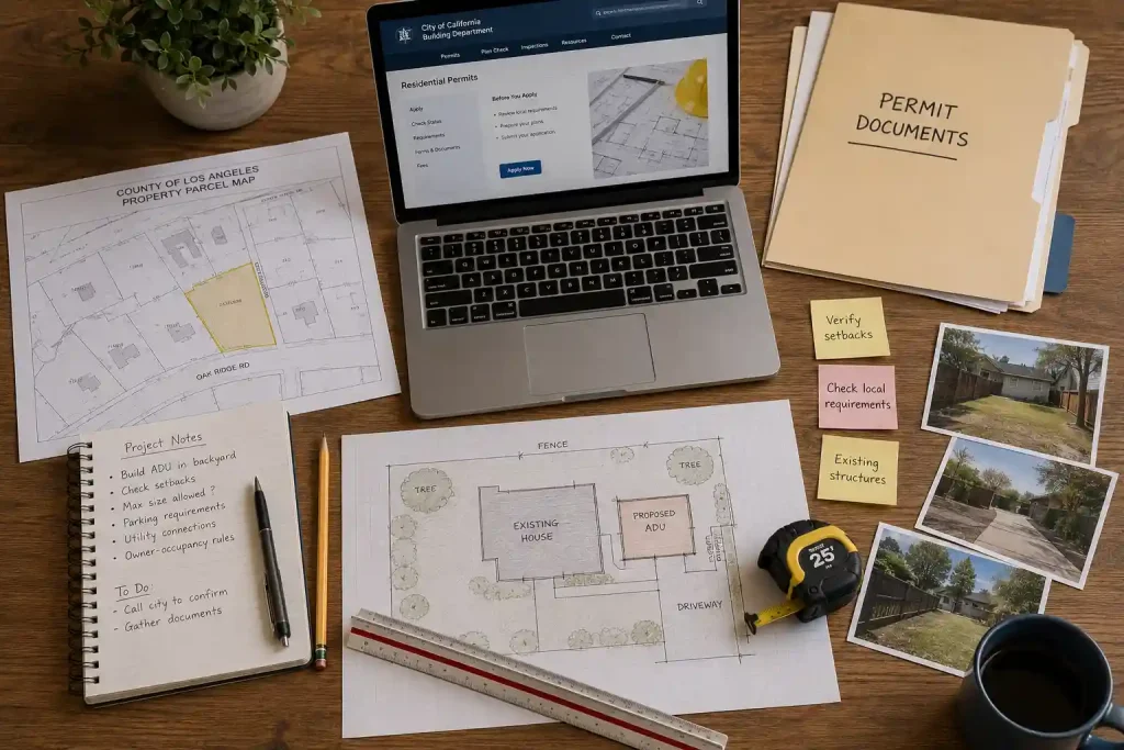
Provide the property address, project type, approximate size, intended location, timeline, and permit status. Helpful files include a survey, assessor map, prior site plan, sketch, contractor drawing, photographs, correction notice, or architectural concept. You can request a quote even when some documents are not yet available.
02
Property and Parcel Research
We review available county and municipal records, parcel mapping, aerial imagery, assessor information, subdivision documents, and client-supplied files. Existing structures and relevant site features are organized into a base plan. If the available information is not reliable enough for the proposed location, we explain what additional survey or measurement is needed.
03
Local Permit Checklist Review
We review available planning, zoning, building, or permit instructions for the project location. This determines the appropriate scale, sheet size, labels, setbacks, calculations, notes, and supporting information for the site-plan portion of the application. Requirements can differ between nearby cities and counties.
04
Draft Existing and Proposed Conditions
The property boundary, house, accessory structures, driveways, walks, fences, and other relevant features are drawn. The proposed project is added from the supplied dimensions and location. Setbacks, access, easements, utilities, coverage, drainage, and project notes are included when applicable.
05
Quality Control and Client Review
The drawing is checked for address, scale, north arrow, dimensions, labels, project scope, existing and proposed linework, title information, and consistency. You review the draft and confirm that the proposed location and dimensions match the intended project before final delivery.
06
Permit-Ready Delivery
The completed site plan is delivered as a high-quality PDF in the required page size. Additional formats can be discussed when needed. A standard residential plan is commonly delivered within 12 to 24 hours after the required information is complete, while complex properties may require more research.
07
Reviewer Corrections and Revisions
If the permit office requests a site-plan correction, send the marked-up drawing, email, or correction notice. Revisions that remain within the original scope are included. A new project location, changed footprint, new structures, grading design, or significant expansion may require an additional quote.
Residential Grading and Drainage Site Plans
Show How the Project Fits the Land Without Misrepresenting Engineering.
Residential site drainage plans range from simple direction arrows to engineered grading packages. The required level depends on the slope, project size, flood conditions, retaining walls, impervious area, soil, drainage system, and local review standards.
Basic Drainage
Existing Flow and Proposed Direction
A basic plan may identify high and low areas, visible swales, downspouts, drainage paths, proposed surface direction, and areas that should remain open. These notes communicate intent but do not replace engineered elevations or calculations.
Topographic Base
Contours and Spot Elevations
Accurate contours, spot grades, building elevations, wall heights, and slope information normally come from a topographic survey. Public elevation data may support early planning but is not a replacement for field information when detailed grading is required.
Civil Engineering
Grading, Stormwater, and Retaining Walls
Detailed finished grades, drainage calculations, pipes, inlets, detention, erosion control, retaining-wall design, flood compliance, and construction details may require a civil or structural engineer. The site plan coordinates the layout with the engineered design.
Neighbor Protection
Do Not Redirect Water Improperly
Residential improvements should not create harmful runoff toward neighboring property, structures, public sidewalks, or foundations. New roofs, patios, driveways, pools, and additions can change drainage and may trigger local stormwater requirements.
Residential Site Plan vs. Other Property Documents
The Site Plan Is Important, but It Is Not Every Drawing Your Permit May Need.
Homeowners often ask for a residential site plan when they actually need several coordinated documents. The site plan shows the project on the property. Architectural plans show the building design. Structural plans explain framing and foundations. A survey establishes legal boundaries and field conditions. Grading plans document elevations and drainage. Understanding the difference helps you order the correct service.
A residential site plan can be created from an existing survey, prior permit plan, subdivision plat, assessor information, client measurements, and available public records when the jurisdiction accepts those sources. The site plan does not certify a property corner or legal boundary. When the project is close to a setback, records conflict, the lot is irregular, or the city requires a stamped survey, a licensed surveyor is necessary.
The site plan also does not include floor plans, elevations, wall sections, structural calculations, foundation plans, energy forms, truss engineering, electrical plans, plumbing plans, or construction details unless specifically added by the appropriate professional. We define the deliverable before beginning so the homeowner knows what the plan covers.
Residential Site Plan
Shows the full lot, structures, proposed project, setbacks, access, easements, utilities, and site relationships.
Boundary or Topographic Survey
Certifies or maps legal property boundaries, monuments, easements, elevations, and field conditions through a licensed surveyor.
Architectural Plans
Show room layouts, elevations, sections, materials, doors, windows, and construction information for the building.
Structural and Engineering Plans
Provide foundations, framing, calculations, retaining walls, grading, drainage, utilities, and other technical design.
Who Prepares a Residential Site Plan?
The Correct Person Depends on the Project, Accuracy, and Required Certification.
A professional drafter can prepare many residential permit site plans when the agency accepts unsealed drawings and reliable property information is available. The drafter converts the records and project dimensions into a clean scaled plan, adds checklist information, and coordinates revisions.
A licensed land surveyor is needed when legal boundary certification, property-corner location, easement confirmation, topographic measurements, or a surveyor's stamp is required. A survey is particularly important when proposed work is close to a property line, the visible fence may not match the boundary, public records conflict, or detailed elevations are needed.
An architect or residential designer may provide the building footprint and architectural plans for an addition, garage, ADU, or new house. A structural engineer may design foundations, framing, walls, and unusual structures. A civil engineer may handle grading, drainage, stormwater, utilities, or difficult access. The site plan brings the property-level information together but does not replace these technical responsibilities.
Some homeowners can draw a simple site plan themselves. The challenge is not drawing a rectangle. The challenge is using the correct property data, understanding the checklist, measuring setbacks from the correct reference, including all relevant improvements, and recognizing when a licensed professional is required.
Drafter for a scaled permit drawing from reliable information
Surveyor for legal boundaries, topography, and field certification
Architect or designer for the building and construction drawings
Engineer for structural, grading, drainage, or technical systems
Residential Site Plan Cost
Standard Permit Site Plan
from $129
Final pricing is confirmed after we review the address, parcel complexity, project type, available documents, and local checklist.
The Price Depends on the Property Information and What the Permit Office Requires.
A standard residential site plan starts at $129. This pricing is suitable for a straightforward residential parcel with accessible public records, a defined project location, and a typical permit checklist. Examples include a shed, fence, deck, driveway, patio, or modest addition where the property conditions and proposed dimensions are clear.
A custom quote may apply when the parcel is very large, irregular, rural, heavily developed, divided into multiple lots, affected by uncertain boundaries, or missing reliable records. Additional work may also be required for several proposed structures, detailed lot-coverage calculations, complex easements, multiple sheets, extensive corrections, flood information, unusual zoning overlays, detailed grading, drainage, retaining walls, or a required CAD deliverable.
The site-plan fee is separate from government permit fees, surveys, architectural drawings, structural engineering, civil engineering, soil reports, energy documents, contractor services, title records, permit expediting, or other third-party costs. Those services solve different parts of the project and may be required depending on local rules.
We confirm the price before drafting begins. The quote identifies what information is included, what the client must provide, and whether the project appears to need a survey or licensed professional. This avoids presenting an inexpensive drafting plan as a complete solution when the permit office requires certified or engineered information.
Standard turnaround is commonly 12 to 24 hours after complete intake. Complex parcels, missing documents, survey coordination, technical requirements, or multiple revision cycles can extend the schedule. Fast delivery does not mean guessing. When the available property information is insufficient, we explain what is needed before finalizing the drawing.
Residential Site Plan Software, Templates, and DIY Drawings
A Template Can Organize the Page, but It Cannot Verify the Property.
Residential site plan templates and free drawing programs can be useful for early planning. They help a homeowner understand common labels, create a rough layout, or explain a project to a contractor. CAD software, online site plan makers, home design applications, GIS maps, PDF tools, and graph paper can all produce a drawing.
The permit office is not approving the software. It is reviewing the information. A polished residential site plan example may not match your jurisdiction, zoning district, parcel, setbacks, easements, project type, or required calculations. Copying a sample can create omissions that are difficult to see until the reviewer issues corrections.
The most common DIY error is using an aerial image or county GIS boundary as though it were a legal survey. Public mapping is valuable for research, but parcel lines may be approximate. Fences, hedges, driveways, and walls may also be offset from the true property boundary. Work close to a setback should not rely on an unverified visual assumption.
A homeowner who prepares the plan should start with the official permit checklist, obtain the best available property documents, draw at a stated scale, show all existing structures, label the proposed work, dimension setbacks, identify easements, and include a north arrow and title information. When the project requires certification or technical design, hire the appropriate professional.
Use templates for organization, not as proof of property facts
Check the official local checklist before drawing
Do not treat fences or GIS lines as certified boundaries
Use surveyors and engineers when legal or technical accuracy is required
Small Omissions Can Create Unnecessary Permit Corrections.
Many site plans are returned because the drawing does not give the reviewer enough reliable information. These are the most common problems we work to prevent.
01
No Defined Scale
A screenshot, sketch, or property image without a stated scale cannot be measured reliably. The reviewer needs a consistent relationship between the drawing and real dimensions.
02
Fence Treated as the Boundary
Fences, hedges, walls, and driveways do not always follow the legal parcel line. Incorrect boundary assumptions can create a setback violation or neighbor dispute.
03
Existing Structures Omitted
The full property context matters. Sheds, garages, pools, patios, decks, retaining walls, and paving can affect coverage, access, separation, drainage, and the available building area.
04
Proposed Work Not Dimensioned
The project should have clear overall dimensions and setback callouts. A reviewer should not need to estimate the location or compare unrelated sketches.
05
Easements Ignored
Utility, drainage, access, sewer, and other easements can limit construction. A project may satisfy zoning setbacks and still conflict with recorded property restrictions.
06
Site Plan Conflicts With Building Plans
The footprint, dimensions, orientation, stairs, porches, and project scope should match the architectural or contractor drawings. Inconsistent sets create review comments and construction confusion.
07
Drainage Changes Not Considered
New roofs, patios, driveways, additions, and walls can redirect runoff. Even a simple plan should consider whether the improvement blocks or changes an existing drainage path.
08
Generic Rules Used Without Local Review
Setbacks and checklists can vary by city, county, zoning district, overlay, project type, lot orientation, and property condition. Generic online information is not a substitute for the reviewing agency.
Nationwide Residential Site Plan Services
Professional Property Plan Drafting Wherever Your Home Is Located.
City Permit Plans provides remote residential site plan drafting across all 50 states. We work with homeowners, builders, contractors, designers, investors, property managers, and permit professionals. The address, available documents, proposed project, and local checklist are reviewed before the scope is confirmed.
Remote drafting works well when reliable parcel information, project dimensions, photographs, and existing documents are available. Some projects still require local fieldwork. A licensed surveyor may need to locate property corners or elevations. An engineer may need to design grading, drainage, retaining walls, or structural systems. An architect may need to prepare the building plans. We identify these dependencies rather than hiding them inside a generic site-plan promise.
All 50 statesRemote research and digital plan delivery
Multiple project typesAdditions, garages, decks, sheds, fences, driveways, pools, and ADUs
Local checklist reviewPlan content adjusted to the jurisdiction
Professional boundariesSurvey, engineering, and architectural needs clearly identified
Residential Site Plan FAQs
Answers About Examples, Cost, Surveys, Software, and Permits.
These questions reflect common homeowner searches about residential site plan drawings, templates, professional preparation, and permit requirements.
A residential site plan is a scaled, top-down drawing of a home property. It shows lot lines, dimensions, the existing house and structures, proposed work, setbacks, access, easements, utilities, drainage information, and permit notes. The plan allows the reviewer to evaluate how the project fits the property.
It normally looks like a property map viewed from above. The sheet includes a parcel outline, the house footprint, existing improvements, the proposed project, dimensions, setback labels, north arrow, scale, legend, notes, and a title block. Proposed and existing features are visually distinguished.
Our standard residential site plan service starts at $129. Larger parcels, irregular lots, incomplete records, detailed coverage calculations, multiple structures, grading, drainage, several sheets, or complex agency requirements may require a custom quote. Surveys, engineering, architectural plans, and government fees are separate.
Check your closing documents, existing survey, prior permit files, builder records, title documents, subdivision plat, assessor records, and county GIS. The local building department may have an older approved plan. If no usable site plan exists, a new drawing can be prepared from available records and project information, with a licensed survey when required.
Some jurisdictions allow homeowner-prepared plans for simple projects. The drawing still needs a reliable boundary source, stated scale, existing structures, proposed work, dimensions, setbacks, easements, north arrow, and checklist information. A survey or professional design may be required when accuracy, certification, grading, drainage, or engineering is involved.
No. A site plan communicates the property layout and proposed project. A licensed survey establishes or certifies legal boundaries, monuments, easements, elevations, and field conditions. A survey can be used as the base for a site plan, and some permits require both documents.
A professional drafter, architect, engineer, surveyor, landscape architect, or homeowner may prepare the plan depending on the project and local rules. A drafter can create the permit drawing from reliable information. Surveying, engineering, legal boundary certification, and professional seals must come from the appropriately licensed professional.
Send the property address, project description, approximate dimensions, intended location, photographs, and any survey, plot plan, assessor map, contractor sketch, architectural plan, prior permit drawing, title document, or city correction notice available. You can request a quote before collecting every file.
Basic drainage arrows, visible swales, existing features, and proposed surface direction can be included when reliable information is available. Detailed contours, finished elevations, retaining walls, pipes, inlets, calculations, flood design, or engineered stormwater systems require topographic survey information and civil engineering when the jurisdiction requires them.
A standard residential site plan is commonly delivered within 12 to 24 hours after complete intake. Complex parcels, missing information, survey coordination, detailed calculations, or several proposed improvements may require additional time. The government permit-review timeline is separate from the drafting turnaround.
Start Your Residential Site Plan
Tell Us What You Are Building and Where It Will Go.
Submit the address and project information you currently have. You do not need a complete permit package to request a quote. We will review the property, proposed work, available documents, and likely drafting requirements before confirming the price.